Iranian Classification Society Rules

< Previous | Contents | Next >
Section 4 Welding Procedure Qualification Tests See Guidance
401. General
1. Application
(1) The welding procedures to be applied to hull construction specified in this Chapter as well as cargo tank, secondary barriers and piping arrangements in ships carrying liquefied gases in bulk, are to be those satisfactorily complying with the welding procedure qualification tests specified in this Section.
![]()
(2) The welding procedures qualification test for areas other than those specified in (1) is to be in accordance with the Guidance in relating to Rules. See Guidance![]()
2. Definitions
(1) Welding procedure specification(WPS)
A specification of materials, detailed methods, welding parameters etc. to be applied in the welding of a particular joint.
(2) Welding procedure qualification tests(WPQT)
A test carried out in order to demonstrate that a weld made according to a specific welding
procedure specification meets the given requirements.
(3) Welding procedure qualification record(PQR)
The record of the actual parameters employed during welding of the qualification test piece ac-
cording to the requirement of (2), and results from the non-destructive inspection and mechan-
ical testing.
3. General requirements of WPQT
(1) The manufacturers are to obtain the approval of the welding procedure qualifications before the welding works in the following case specified in (a) through (b)
(a)
(b)
Where the welding procedure is first adopted for welding works specified in 1.
Where the welding variables specified in 402. 2 (1) through (11) are changed beyond the extent of those described in the approved welding procedure specifications.
(2) For the approval of welding procedure qualification, the preliminary welding procedure specifica- tion specified in 402. is to be reviewed by the Society and the welding procedure qualification
test is to be carried out with satisfactory results. Welding procedure specifications are to refer
to the test conditions and test results achieved during welding procedure qualification testing.
402. Welding procedure specification
1. A welding procedure specification (WPS) is to be prepared by the shipyard or manufacturer which intends to perform the welding procedure qualification test. This document is also referred to as a preliminary welding procedure specification (pWPS). The shipyard or manufacturer is to submit to the Society a pWPS for review prior to the tests.
2. The pWPS can be modified and amended during procedure tests as deemed necessary however it is to define, at least, the following welding variables.
(1)
(2)
(3)
(4)
(5)
(6)
Kind of base metal
Nominal thickness or diameter range(dimensions) Welding process
Joint or groove designs with tolerances
Welding position(s) and direction of progression
Welding consumables(grade, shielded gas, backing, flux, etc.)
(7) Electrical characteristics(amperage, voltage and pole nature etc.)
(8)
(9)
Travel speed and heat input ranges
Preheat and maximum interpass temperature
(10) Post weld heat temperature (if any)
(11) Other conditions necessary for the welding procedure (ex. : welding speed, heat input etc.)
3. Welding consumables used in welding procedure qualification tests should be approved in accord- ance with the requirements specified in Sec 6 of the Rules.
4. In case that the test pieces welded according to the pWPS show unacceptable results the pWPS is to be adjusted by the shipyard or manufacturer. The new pWPS is to be prepared and the test pieces welded in accordance with the new pWPS.
5. The WPS is to be used as a basis for the production welds, and upon satisfactory completion of the tests based on the pWPS, the Society may approve it as a WPS. In case that a WPS is ap- proved by the Society the approval range is to be in compliance with the requirements in 407.
![]()
120 Rules for the Classification of Steel Ships 2015
![]()
403. Welding procedure qualification tests(WPQT)
1. Where procedure qualification test is required, the test assembly is to be welded in the same or similar environment and the qualification tests are to be carried out under the welding conditions given in the pWPS.
2. Welding of the test assemblies and testing of test specimens are to be witnessed by the Surveyor.
3. If tack welds and/or start and stop points are a condition of the weld process they are to be fused into the joint and are to be included in the test assemblies.
4. For qualification tests for stainless clad steels, the requirements specified in 404. and 405. are to be complied with. However the impact test may be dispensed with where other welding procedure qualification on the stainless clad steel base metal under the same welding condition has been approved.
![]()
![]()
5. Where materials other than those specified in this Section are used, the qualification tests are to be carried out in accordance with the testing standard approved by the Society. Duplex stainless steel is to be in accordance with the Guidance in relating to Rules. See Guidance
6. Tests or test conditions other than those specified in this Section for the welding procedure qual- ification may be required, where deemed necessary by the Society.
404. Tests for butt welded joints
1. Application
The requirements stated hereunder apply to the butt joints welded by manual welding, semi-auto- matic welding or automatic welding.
2. Kinds of test
According to the materials to be tested, kinds of test and number of test specimens are to be giv-
![]()
en in Table 2.2.4. Additional test may be required where found necessary by the Society.
Guidance
3. Test assemblies
![]()
See
(1) Test assemblies are to be prepared with the work.
same or equivalent material used in the actual
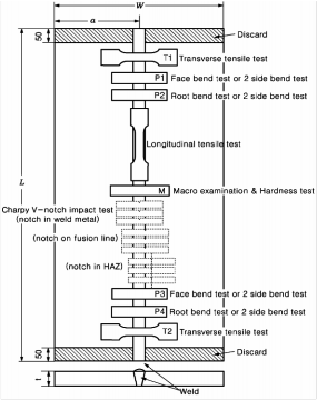
(2) The dimensions and types of test assembly are to be as indicated in Fig 2.2.6.
(Note)
The test assembly is to be of a size with the minimum dimensions:
(1) manual or semi-automatic welding: Width(W) : min. 300mm Length(L) : min. 350mm
(2) automatic welding Width(W) : min. 400mm Length(L) : min. 1,000mm
(A) Test assembly for Hull Structural Steels, High Strength Quenching and Tempered Steels, Stainless Steels or Aluminium Alloys
Fig 2.2.6 Welding procedure test assembly (Unit : mm) (cont'd)
![]()
Rules for the Classification of Steel Ships 2015 121
![]()
(B) Test assembly for pipes up to 20mm in thickness
(C) Test assembly for pipes over 20mm in thickness
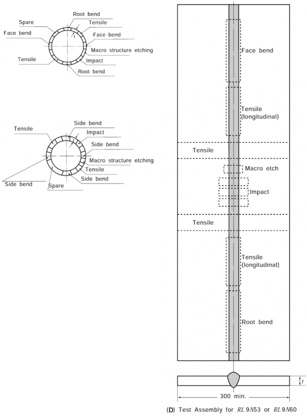
Fig 2.2.6 Welding procedure test assembly (Unit : mm)
![]()
122 Rules for the Classification of Steel Ships 2015
![]()
Table 2.2.4 Kinds of Test for Butt Welded Joints
Grades and material symbols of test specimens | Kinds and number of specimens for test(1) | ||||||||
Visual insp. | Tensile test | Bend test | Impact test | Macro- structure insp. | Hard. test | Non- destructive insp.(3) | |||
Rolled steels for hull structural | Normal strength steel | A , B , D , E | Welding positions of whole length | 2 | 4(2) | (3) | 1 | - | Welding positions of whole length |
Higher strength steel | A H 32, D H 32, E H 32, F H 32, A H 36, D H 36, E H 36, F H 36, A H 40, D H 40, E H 40, F H 40 | 1(11) | |||||||
Rolled steels for low temperature service | RL235A, RL235B, RL325A, RL325B, RL360, R L 2N 255, RL 3N 255, RL 3N 275, RL 3N 440, RL 5N 590 | 2 | - | ||||||
R L 9N 520, R L 9N 590 | 4(5) | ||||||||
Steel pipes for low temperature service | R L P A , R L P B , R L P C , R L P 2, R L P 3, R L P 9 | 2 | 4(2) | ||||||
Weldable high strength quenched and tempered steel | A H 43, D H 43, E H 43, F H 43, A H 47, D H 47, E H 47, F H 47, A H 51, D H 51, E H 51, F H 51, A H 56, D H 56, E H 56, F H 56, A H 63, D H 63, E H 63, F H 63, A H 70, D H 70, E H 70, F H 70 | 1(11) | |||||||
Casting for welded construction and Hull steel forging | R S C 410, R S C 450, R S C 480, R S C 520, R SC 560, R SC 600, R SC 440A , R S C 480A , R S C 550A , R SF 410H , R SF 450H , R S F 480H , R S F 520H , R SF 560H , R S F 600H , R SF 550A H , R SF 600A H , R S F 650A H | (3)(10) | |||||||
- | |||||||||
Rolled stainless steels | R S T S 304, RSTS 304L, RSTS 304N 1, RSTS 304N 2, RSTS 304L N , RSTS 309S, RSTS 310S , RSTS 316, RSTS 316L , RSTS 316N , RSTS 316L N , RSTS 317, RSTS 317L, RSTS 317L N , RSTS 321, RSTS 347 | 2 | (6) | ||||||
Stainless steel pipes | R S T S 304T P , R ST S 304LT P , R ST S 309S T P , R S T S 310ST P , R ST S 316T P , R ST S 316LT P , R S T S 317T P , R ST S 317LT P , R ST S 321T P , R S T S 347T P | 4 | |||||||
Aluminium alloys(7) | 5000 series | 5083P , 5383P , 5059P , 5086P , 5754P , 5083S , 5383S , 5059S, 5086S(8) | 4(2) | - | |||||
6000 series | 6005AS, 6061S, 6082S (9) | ||||||||
NOTES: (1) Where found necessary by the Society, microscopic test, hardness test and tests other than these may be required. See Guidance (2) Two root and two face bend specimens are to be tested. For thickness 12 mm and over, four side bend speci- mens may alternatively be tested. (3) No. of test sets and position of notch are as shown in Fig 2.2.7. (4) Internal inspections by radiographic examination or ultrasonic examination and surface inspections by magnetic particle examination or liquid penetrant examination are to be carried out. (5) Two specimens are to be taken longitudinally and transversely respectively (See. Fig 2.2.6) (6) Where found necessary by the Society, impact tests up to steels specially used for may be required. See Guidance (7) Material symbols of aluminium alloys include the symbols of which is the temper condition. (8) Rolled products which have the same grade and temp condition may be used. (9) Other rolled aluminium alloys of 6000 series with minimum tensile strength 260 (10) Where impact test is required. (11) Hardness test( 10) is required for weldable high strength quenched and tempered steel and hull structural steel with specified minimum yield strength of | |||||||||
![]()
![]()
![]()
![]()
![]()
![]()
![]()
Rules for the Classification of Steel Ships 2015 123
![]()
(3) Test assemblies are to be welded in the same welding positions as the actual work.
(4) Test assemblies for the pipes over 500 mm in diameter at the actual work may be those for the plates.
(5) For butt welded joints of rolled steel plates, the direction of welding according to rolling direc- tion is to be as follows.
(a) When steel plates impact tested in longitudinal direction are used for test assemblies, the di-
rection of welding of test assembly is perpendicular to the rolling direction of the two plates.
(b) When steel plates impact tested in transverse direction are used for test assemblies, the di-
rection of welding of test assembly is parallel to the rolling direction of the two plates.
4. Visual inspection
Welding surface is to be regular and uniform surface and is to be free from injurious defects, such as cracks, undercuts, overlaps, etc.
5. Tensile tests
(1) The number of tensile test specimens taken from each test assembly is to be as shown in
Table 2.2.4.
(2) Tensile tests are to be carried out with the test specimen shown in strength is not to be less than the minimum tensile strength specified
Table 2.2.1. The tensile for the base metal except
for those specified in Table 2.2.5. When butt welds are made between plates of different
![]()
grades, the tensile strength to be obtained on the welded assembly is to be in accordance the requirements relating to the steel grade having lower strength. See Guidance![]()
![]()
![]()
Table 2.2.5 Tensile Test Requirements for Butt Welded Joint
with
Kind of testing materials | Grade of testing materials | Tensile strength ( ) | Yield strength ( ) |
Rolled steels for lower temperature service | RL9N520, RL9N590 | 590 min.(1) | 315 min. |
630 min.(2) | - | ||
Steel pipes for low temperature service | RLP 9 | 630 min. | - |
Aluminium alloys | 5754 | 190 min. | - |
5086 | 240 min. | - | |
5083 | 275 min. | - | |
5383 | 290 min. | - | |
5059 | 330 min. | - | |
6005A, 6061, 6082(3) | 170 min. | - | |
(Notes) (1) For test specimen in longitudinal direction (2) For test specimen in transverse direction (3) See notes (9) of Table 2.2.4. | |||
![]()
(3) In those cases where the consumables are not unavoidably approved by the Society, it is to be required additionally to prepare a R 14A deposited metal tensile test specimen as shown in Table 2.2.1 in entirely weld metal and the tensile properties recorded for each specimen are not to be less than the minimum required for the approval of the appropriate grade of consumable. Where more than one welding process or type of consumable has been used to make the test weld, test specimens are to be taken from the area of the weld where each was used with the exception of those processes or consumables used to make the first weld run or root deposit. See Guidance![]()
6. Bend tests
(1) The number of bend test specimens taken from each test assembly is to be as shown in Table 2.2.4, and the position of specimen is to be as shown in Fig 2.2.6.
![]()
124 Rules for the Classification of Steel Ships 2015
![]()
(2) The shape and dimension of face bend specimen, root bend specimen or side bend specimen are to be as indicated in RB1, RB2 or RB3 of Table 2.2.2. Bend test procedure and inside bend
radius are to be as indicated in Table 2.2.6.
greater than 3 mm in length in any direction on
There is to be no crack nor any other defect the surface of bend specimen.
Table 2.2.6 Bend Test Requirements
Kind of testing materials | Grade of testing materials | Inside bend radius (mm)(1) | Bending angle |
Steel pipes for low temperature service | R L P 9 |
| 180° |
weldable high strength quenched and tempered steel | A H 56, D H 56, E H 56, F H 56, A H 63, D H 63, E H 63, F H 63, A H 70, D H 70, E H 7 0, F H 70 |
| |
Aluminium alloys | 5754, 5086, 5083, 5383, 5059, 6005A, 6061, 6082(2) | (3) | |
Other materials |
| ||
NOTES : (1) (2) See Notes (9) of the Table 2.2.4. (3) The bend test specimens should be bent on a mandrel with maximum diameter as given in the formula below.
where is the maximum former diameter is the thickness of the bend test specimen (this includes side bends) is the minimum tensile elongation required by the alloy grade, temper condition and thickness (for combination between different alloys, the lowest individual value should be used). | |||
(3) For butt joints in heterogeneous steel plates, face and root longitudinal bend test be used instead of the transverse bend test specimens.
7. Impact tests
(1) Normal and higher strength hull structural steels
(a) The test specimen is to be charphy V-notch impact test specimen as shown and to be taken from the position in Fig 2.2.6.
![]()
specimens may
in Table 2.1.3
(b) The number of test specimens taken from test assemblies and the position of notch for the
test specimen are as specified in Fig 2.2.7.
(c)
(d)
(e)
(f)
(g)
Test specimen is to be sampled from 1 to 2 mm below the surface of the base metal, trans- verse to the weld and on the side containing the last weld run.
Test temperature and absorbed energy are to be in accordance with Table 2.2.7.
When butt welds are made between different steel grades/types, the test specimens are to be taken from the side of the joint with lower toughness of steel. Temperature and absorbed
energy results are to be in accordance with the requirements for the lower toughness steel.
![]()
![]()
See Guidance
Where more than one welding process or consumable has been used to make the test weld, impact test specimens are to be taken from the respective areas where each was employed. This is not to apply to the process or consumables used solely to make the first weld run or root deposit.
Where the weld metal cross-section size or shape does not allow the charphy V-notch im-
pact test specimen to be in deposited metal, the requirements in
applied.
202. 3 of Ch 1 are to be
![]()
Rules for the Classification of Steel Ships 2015 125
![]()
(2) High strength quenched and tempered steels
(a) Impact test is to be performed as described in the above (1).
(b) Test temperature and absorbed energy are to be in accordance
metal
(3) Weldable C and C-Mn hull steel castings and forgings
For base metal with specified impact values test temperature and
accordance with the requirements of the base metal to be welded.
![]()
![]()
![]()
with the requirements of base absorbed energy are to be in
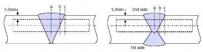
heat input | thickness | Locations of V-notch(3) | |
normal heat input 50 | t | 50 mm(1) |
|
t > 50 mm | |||
high heat input > 50 | t | 50 mm(2) | |
t > 50 mm | |||
Note: (1) For one side single run welding over 20 mm notch location "a" is to be added on root side. (2) For one side welding with thickness over 20 mm notch locations "a", "b" and "c" are to be added on root side. (3) Notch locations: a : center of weld "WM" b : on fusion line "FL" c : in HAZ, 2 mm from fusion line d : in HAZ, 5 mm from fusion line e : in HAZ, 10 mm from fusion line in case of heat input > 200 kJ/cm | |||
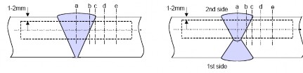
Fig 2.2.7 No. of test sets and locations of V-notch
![]()
126 Rules for the Classification of Steel Ships 2015
![]()
![]()
![]()
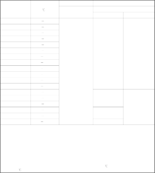
Table 2.2.7 Impact test requirements for butt joints (t 50
mm)(1),(2)
Grade of steel | Test temp. ( ) | Value of minimum average absorbed energy (J) (4) | |||
For manually or semi-automatically welded joints | For automatically welded joints | ||||
Downhand, Horizontal, Overhead | Vertical upward, Vertical downward | ||||
A(3) | 20 | 47 min. | 34 min. | 34 min. | |
B (3), D | 0 | ||||
E | -20 | ||||
A H 32, A H 36 | 20 | ||||
D H 32, D H 36 | 0 | ||||
E H 32, E H 36 | -20 | ||||
F H 32, F H 36 | -40 | ||||
A H 40 | 20 | 39 min. | 39 min. | ||
D H 40 | 0 | ||||
E H 40 | -20 | ||||
F H 40 | -40 | ||||
Note: (1) For thickness above 50 mm impact test requirements are to be agreed by the Society. See Guidanc e (2) These requirements are to apply to test piece of which butt weld is perpendicular to the rolling direc- tion of the plates. (3) For Grade A and B steels average absorbed energy on fusion line and in heat affected zone is to be minimum 27 J. (4) When the absorbed energy of two or more test specimens among a set of test specimens is less in val- ue than the specified average absorbed energy or when the absorbed energy of a single test specimen is less in value than 70 % of the specified average absorbed energy, the test is considered to have failed. | |||||
![]()
![]()
(4) Steels for low temperature Service
(a) The test specimen is to be charphy V-notch impact test specimen and to be taken from the position in Fig 2.2.6.
as shown in Table 2.1.3
(b) The number of test specimens taken from test assemblies, the position of notch for the test specimen, test temperature and absorbed energy are as specified in Table 2.2.8.
(5) Rolled stainless steels and stainless steel pipes
(a) Where deemed necessary by the Society, impact test may be required.
(b) Test temperature and absorbed energy are to be in accordance with the requirements of base metal
8. Macro-structure inspection
(1) The test specimens are to be prepared and etched on one side to clearly reveal the weld metal, the fusion line and the heat affected zone. Macro examination is to include about 10 mm un- affected base metal.
(2) The examination is to reveal a regular weld profile, through fusion between adjacent layers of weld and base metal and the absence of defects such as cracks, lack of fusion etc.
![]()
![]()
9. Non-destructive inspection See Guidance
(1) Test assemblies are to be examined for the whole length(excepting discard area of test assembly of Fig 2.2.6) by visual and by non-destructive testing prior to the cutting of test specimen. Non destructive examinations should be carried out after any required post weld heat treatment, natural or artificial ageing, and prior to the cutting of the test specimens.
![]()
(2) For high strength quenched and tempered steels with
and above the non-destructive testing is to be
specified minimum yield strength of 420
delayed for a minimum of 48 hrs, unless
![]()
Rules for the Classification of Steel Ships 2015 127
![]()
heat
Table 2.2.8
treatment has been carried out.
Impact Test Requirements for Butt Welded Joint (Steels for low temperature Service)
A(1) B, C, D , E(1)
( )(4)
Grade of steel Test temp.
Value of average absorbed energy(J)(3)
Value of average absorbed energy(J)(3)
L(2) T(2)
RL 235A 40
RL 235B 50
RL 325A 50
RL 325B 60
RL 360 60
RL 2N255 70
RL 3N255 101
RL 3N275 101
RL 3N440 110
RL 5N590 130
RL 9N520 196
RL 9N590 196
RLPA 40
RLPB 50
RLPC 60
RLP 2 70
27 min.
41 min. 27 min.
27 min.
-
RLP 3 95
34 min.
RLP 9 196 41 min.
NOTES:
(1) Position of notch as shown in Fig 2.2.7.
(2) L(or T) indicates that the direction of welding is transverse (or parallel) to the rolling direction of test materials.
(3) When the absorbed energy of two or more test specimens among a set of test specimens is less in value than the specified average absorbed energy or when the absorbed energy of a single test specimen is less in value than 70% of the specified average absorbed energy, the test is considered to have failed.
(4) Where requirements in Pt 7, Ch 5 apply, the impact test temperature is to be as given as follows:
(a) Impact test temperature for R L 24A through R L 5N43 is to be the lower of the temperatures given in
Table 2.1.18 specified in Pt 2, Ch 1.
(b) Impact test temperature for R LP A through R LP C is to be either 5 below the design temperature or
-20 whichever is the lower.
(3) NDT procedures are to be agreed with the Society. The results of non-destructive testing
are to
show that there are no cracks or other injurious defects, and acceptance criteria is to be in ac- cordance with the relevant requirements of the relevant Rules.
![]()
![]()
10. Hardness test See Guidance
(1) Fspoerciwfiedldamblienimhiugmh
![]()
![]()
ystireeldngtshtreqnugethnchoefdRaenHd te3m55pered ste,elhaarnddneshsultlesst(trthuectuvriaclkerrosllemdetshtoedelsHvw1i0th)
is to be carried out in accordance with the Guidance relating to the Rules specified by the Society.
(2) The results from the hardness test are not to exceed the following:
![]()
128 Rules for the Classification of Steel Ships 2015
![]()
- Steel
- Steel
![]()
![]()
with a specified minimum yield strength ReH 420 : 350 Hv10
with a specified minimum yield strength 420 < ReH 690 : 420 Hv10
405. Tests for fillet welded joints
1. Application
The requirements stated hereunder apply to the fillet joints welded by manual, semi-automatic or automatic welding in any welding position.
2. Kinds of test
![]()
![]()
Fillet weld joints are to be subjected to visual inspection, surface crack detection, macro-structure inspection, hardness test and fracture test. Additional tests may be required if found necessary by the Society. See Guidance
3. Test assemblies and welding
(1) Test assembly is to be prepared with the same or equivalent material used in the actual work.
(2) Dimensions and type of test assembly are to be as indicated Fig 2.2.8.
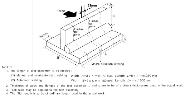
Fig 2.2.8 Test assembly for fillet weld joint (unit : mm)
(3) Test assembly is to be welded in the same welding positions as the actual work.
(4) The assembly is to be welded on one side only, except in case deemed necessary surveyor.
by the
(5) For single run manual and semi-automatic welding, a stop/restart is to be included in the test
length and its position is to be clearly marked for subsequent examination.
4. Visual inspection
Fillet welding is to have a regular and uniform surface, and is to be free from cracks, undercuts, overlaps and other injurious defects.
5. Non-destructive inspection
(1) Test assemblies are to be examined by visual and by non-destructive testing prior to the cutting of test specimen. In case that any post-weld heat treatment is required or specified non-destruc- tive testing is to be performed after heat treatment.
![]()
(2) For weldable high strength quenched and tempered steel with specified minimum yield strength of 420 and above the non-destructive testing is to be delayed for a minimum of 48 hrs,
![]()
Rules for the Classification of Steel Ships 2015 129
![]()
unless heat treatment has been carried out.
(3) NDT procedures are to be agreed with the Society. The results of non-destructive testing are to show that there are no cracks or other injurious defects, and acceptance criteria is to be in ac- cordance with the relevant requirements of the relevant Rules.
6. Macro-structure inspection
(1) The test specimen is to be taken from the position in Fig 2.2.8. However, in case of rolled steels for hull structural, weldable high strength quenched and tempered steel, and aluminium al- loy, two specimens are to be taken. For manual welding and semi-automatic welding, one of the macro etched specimens is to be from the stop/restart position, if present.
(2) The test specimens are to be prepared and etched on one side to clearly reveal the weld metal, fusion line, root penetration and the heat affected zone. Macro examination is to include about 10 mm unaffected base metal.
(3) The examination is to reveal a regular weld profile, through fusion between adjacent layers of weld and base metal, sufficient root penetration and the absence of defects such as cracks, lack of fusion etc.
7. Hardness test
![]()
![]()
![]()
Ffioedr wmeilndiambulemhyigiehldstrsetrnegntghthquoefncRheeHd an3d55tempered, shtaeredlnaenssd theustl(lHsvtru1c0tu) raisl cordance with the requirement in 404. 10. See Guidance
Fracture tests 8.
trollbeed csatererilesdwoiutht isnpeacci--
The remaining test assemblies after the macro-structure test specimen has been removed are to be
broken by pressing as shown in Fig 2.2.8 and it shall be evaluated cracks, blow holes, poor pene- trations and any other injurious defects in the fractured surface. And imperfections that are detected
should be assessed in accordance with KS B ISO5817, class B.
406. Retests and Procedure qualification records(PQR)
1. Retests
(1) Where visual inspection or non-destructive inspection fails to meet the requirements, the new test specimens welded under the same welding condition, are to be subject to retest and all of these test specimens are to pass the test. If this additional test piece does not comply with the relevant requirements, the pWPS is to be regarded as not capable of complying with the re- quirements without modification.
(2) Where the result of a tensile or bend test does not comply with the requirements, twice as many test specimens as the number of specimens of failed test are to be selected from either the first test material or test materials welded under the same welding conditions, and all of these test specimens are to be satisfactorily tested.
(3) If there is a single hardness value above the maximum values allowed, additional hardness tests are to be carried out (on the reverse of the specimen or after sufficient grinding of the tested surface). None of the additional hardness values is to exceed the maximum hardness values required.
(4) (a) Where the result of the impact test is unsatisfactory, additional tests may be carried out, with the exception of the cases specified in (i) and (ii) below, by taking a set of test speci- mens out of the same test material from which the above-mentioned test specimens have been taken.
(i) The absorbed energy of all test specimens is under the required average absorbed energy.
(ii) The absorbed energy of two of the test specimens is under 70 % the required average
absorbed energy.
(b) In case of the previous (a), the test specimens may be accepted, provided that the average
absorbed energy of the six test specimens, including those which have been rejected as un- satisfactory, is not less than the required average absorbed energy, and that not more than two individual results are lower than the required average absorbed energy and of these, not
![]()
130 Rules for the Classification of Steel Ships 2015
![]()
more than one result is below 70 % of the required average absorbed energy.
(5) Where there is insufficient welded assembly remaining to provide additional test specimens, a further assembly is to be welded using the same procedure to provide the additional specimens.
(6) Where the retest fails to meet the requirements, the test may be made over again. In this case, where the whole tests specified on the test assembly are carried out and are complied with re- quirements, the tests are accepted as successful.
2. Procedure qualification records(PQR)
![]()
(1) Three copies of the procedure qualification records showing the welding conditions for test as- semblies and test results are to be submitted to the Society for approval. Forms of welding pro- cedure test records are to be at the discretion of the Society. See Guidance![]()
(2) A statement of the results of assessing each test piece, including repeat tests, is to be made for each welding procedure test. The relevant items listed for the WPS of these requirements are to be included.
(3) A statement that the test piece was made according to the particular welding procedure is to be signed by the Surveyor witnessing the test and is to include the Society´s identification.
407. Validity of qualified welding procedure specification
1. General
(1) Welding procedures qualified at a manufacturer are valid for welding in workshops under the same technical and quality management.
(2) Qualification of a welding procedure remains valid provided the welding variables are kept with-
in the qualified range during production welding. When one or more variables outside the quali- fied range given in 2. occur, the welding procedure is to be respecified and requalified by welding procedure qualification tests.
(3) Shop primers may have an influence on the quality of fillet welds and is to be considered.
Welding procedure qualification with shop primer will qualify those without but not vice versa.
![]()
![]()
(4) Validity of welding variables for the welding procedure specification of aluminium alloy is to be in accordance with the Guidance relating to Rules. See Guidance
2. Validity of variables for qualified WPS is as follows. However, it may be considered as equiv- alent for the requirements of the standard internationally recognized(A W S, A SM E etc.) are applied.
![]()
(1) Base metal Kind of base metal and their validity are as follows. Other materials not specified herein is to be in accordance with the requirements of the standard internationally recognized as deemed appropriate by the Society. See Guidance![]()
![]()
(a) Normal and higher strength hull structural steels
![]()
![]()
Normal strength steel(A , B , D and E ) or equivalent structural steels with tensile strength 400 ~ 520 .
Higher strength steels(A H 32, D H 32, E H 32, F H 32, A H 36, D H 36, E H 36, F H 36,
![]()
![]()
A H 40, D H 40, E H 40 and F H 40) or equivalent structural steels with minimum specified yield strength 315 ~ 390 .
![]()
Weldable high strength quenched and tempered steels (Pt 2, Ch 1, 308. of the Rules) or equivalent structural steels with minimum specified yield strength 420~690
.
(i) For each strength level, welding procedures are considered applicable to the same and
lower toughness grades as that tested.
(ii) For each toughness grade of normal and higher strength hull structural steels, welding
procedures are considered applicable to the same and two lower strength levels as that tested.
(iii) For each toughness grade of high strength quenched and tempered steels, welding proce-
dures are considered applicable to the same and one lower strength level as that tested.
(iv) For applying the above (a) and (b) to high heat input processes above 50 kJ/cm, e.g.
the two-run technique with electro slag and electro gas
either submerged arc or gas shielded metal arc welding, welding, welding procedure is applicable to that toughness
grade tested and one strength level below.
![]()
Rules for the Classification of Steel Ships 2015 131
(b)
(c)
(d)
(e)
![]()
(v) For the high strength quenched and tempered steels, the approval of quenched and tem- pered steels does not quality thermo-mechanically rolled steels (TMCP steels) and vice versa.
Weldable C and C-Mn hull steel castings
(i) Welding procedures are considered applicable to the same and lower strength level as that tested.
(ii) The approval of quenched and tempered hull steel castings does not quality other deliv- ery conditions and vice versa.
Weldable C and C-Mn hull and general purpose steel forgings
(i) Welding procedures are considered applicable to the same and lower strength level as that tested.
(ii) The approval of quenched and tempered hull steel forgings does not quality other deliv- ery conditions and vice versa.
Rolled steels for low temperature service and Steel pipes for low temperature service Rolled stainless steels and Stainless steel pipes
(2) Thickness and outer diameter of base metal
(a) The qualification of a WPS carried out on a plate or pipe test assembly of thickness valid for the thickness range given in Table 2.2.9
t is
Table 2.2.9 Qualified thickness range for butt, T-joint and fillet welds
Thickness of test piece,
Range of approval (mm)
(mm) (1)
Butt and T-joint welds with single
run or single run from both sides
Butt and T-joint welds with
multi-run and fillet welds (2)
3 0.8 1.1 2
3 < 12 0.7 1.1 3 2
12 < 100 0.7 1.1 (3) 0.5 2 (max.150)
100 < 0.8 1.1 (3) 0.5 1.5
Notes ;
(1) For multi process procedures, the recorded thickness contribution of each process is to be used as a basis for the range of approval for the individual welding process.
(2) For fillet welds, the range of approval is to be applied to both base metals.
(3) For high heat input processes over 50 kJ/cm, the upper limit of range of approval is to be 1.0 x .
(b) In addition to the requirements of Table 2.2.9, the range of approval of throat thickness "a" for fillet welds is to be as follows:
(i) Single run ; "0.75 x a" to "1.5 x a"
(ii) Multi-run ; as for butt welds with multi-run (i.e. a=t)
(c) The qualification of a WPS carried out on a pipe test assembly is valid for the outer diam-
eter range given in Table 2.2.10.
![]()
![]()
Table 2.2.10 Qualified outer diameter range for pipe welds
Outer diameter D (mm) | Qualified range | |
D | 168.3 | 0.5 D 2 D |
D | 168.3 | 0.5 D |
![]()
(d) For the vertical-down welding, the test piece thickness "t" is always taken as the upper lim- it of the range of application.
(e)
(f)
For unequal plate thickness of butt welds the lesser thickness is ruling dimension.
Notwithstanding the above, the approval of maximum thickness of base metal for any tech- nique is to be restricted to the thickness of test assembly if three of the hardness values in
![]()
132 Rules for the Classification of Steel Ships 2015
![]()
the heat affected
404. 10 (2) and
(3) Welding positions
zone are found to be within 25 Hv of the maximum permitted, as stated
405. 7 of the Rules.
Approval for a test made in any position is restricted to that position (see Fig 2.2.9 and Fig
2.2.10 of the Rules). To qualify a range of positions, test assemblies are to be welded for highest heat input position and lowest heat input position and all applicable tests are to be made on those assemblies.
(4) Welding process
(a) The approval is only valid for the welding process(es) used in the welding procedure test. It is not permitted to change from a multi-run to a single run.
(b) For multi-process procedures the welding procedure approval may be carried out with sepa- rate welding procedure tests for each welding process. It is also possible to make the weld- ing procedure test as a multi-process procedure test. The approval of such a test is only valid for the process sequence carried out during the multi-process procedure test.
(5) Welding consumables
(a) Except high heat input processes over 50 kJ/cm, welding consumables cover other approved welding consumables having the same grade mark including all suffixes specified in Pt 2, Ch 2, Sec 6 of the Rules with the welding consumable tested.
(b) Change in welding consumables specified in sumables) of Pt 2, Ch 2 of the Rules.
Table 2.2.3(Application of welding con-
(c) Change in shielding gas in accordance with Pt 2, Ch 2, 603. 3 (4) of the Rules.
(6) Welding condition
(a)
Change from short circuiting transfer to spray arc or pulsed arc or vice versa.
(b)
(c)
![]()
![]()
![]()
Change of welding voltage, current and/or travel speed are to be Society. See Guidance
![]()
The minimum preheating temperature is not to be 15 less qualification. The maximum interpass temperature is not to be 56 the qualification
at the discretion of the
than that used in the higher than that used in
(d) The heat treatment used in the qualification test is to be maintained during manufacture.
Holding time may be adjusted as a function of thickness.
(7) Heat input
(a) The upper limit of heat input approved is 25 % greater than that used in welding the test piece or 55 kJ/cm whichever is smaller, except that the upper limit is 10 % greater than that for high heat input processes over 50 kJ/cm.
(b) The lower limit of heat input approved is 25 % lower than that used in welding the test piece.
(8) Type of joint
(a) Range of approval depending on type of welded joints for test assembly is to be specified in Table 2.2.11
(b) A qualification test performed on a butt weld will also qualify for fillet welding within the thickness ranges specified for fillet welds specified in (2) (a) above.
Table 2.2.11 Range of approval for type of welded joint
Type of welded joint for test assembly | Range of approval | |||
Butt welding | One side | With backing | A | A, C |
Without backing | B | A, B, C, D | ||
Both side | With gouging | C | C | |
Without gouging | D | C, D | ||
![]()
Rules for the Classification of Steel Ships 2015 133
![]()
![]()
![]()
(c) Change of specified type of joint which may significantly affect penetration and fusion etc, of the weld. However decrease in the groove angle, decrease in the root opening or increase in root face is to be as deemed appropriate by the Society. See Guidance
(9) Others The Validity relating to the welding variables other than previous (1) to (8) may com-
ply with the requirements of the internationally recognized Code (AWS, A S ME , ISO, E N etc.)
3. For changes other than previous 2, the welding procedure qualification test may be dispensed with.
In this case, the welding procedure specification to which the related procedure qualification cord(PQR) is attached is to be requalified.
re-
408. Welding procedure qualification test for YP47 Steel Plates
![]()
![]()
The welding procedure qualification test for YP47 Steel Plates is to be in accordance with the Guidance in relating to Rules. See Guidance
![]()
134 Rules for the Classification of Steel Ships 2015
![]()